
Stepper Motors
Controller Board
LCD Pins
Extruder Information
Hotend Thermistor
Fans
Heated Bed
Repetier Firmware
Stepper Motors
V1 Units
I never ever found a data sheet for the specific black motors. On of the very early pictures of the i3 showed a different motor used for the extruder that had a big honking label on it and zooming in on the picture you could read the number, and it also stated 1.3A rated right on the motor. Well, that motor did have a data sheet and it specified the coil resistance and inductance. Upon getting my actual shipping version of the i3, I measured the black motors now used and they matched the electrical specs of the original motor. Then I further used the stepper driver data sheets and noted the current sensing resistors used, measured the stock Vref voltage my boards shipped with, did the math, and worked out they were driving the same 1.3A rating on the black motors.
Stepper motor part# BOHONG 42HB34F103AB
Current of the Stepper motors is 1.3A
Melzi stepper driver default VREF voltage is 0.83VDC (equates to 1.3A drive)
V2 Units
The V2 units seem to be shipping with a different stepper motor with less current. It has also been noted that the controller boards where not necessarily adjusted correctly for these new motors and are over driving them and getting hot. The steppers in the newer models are labeled as the following (if you have this version you should check the stepper driver vref settings):
JINSANSHI MOTOR
42HS34(L)-0954JA05-D21
LOT NO. 151006
Controller Board
V1 Units
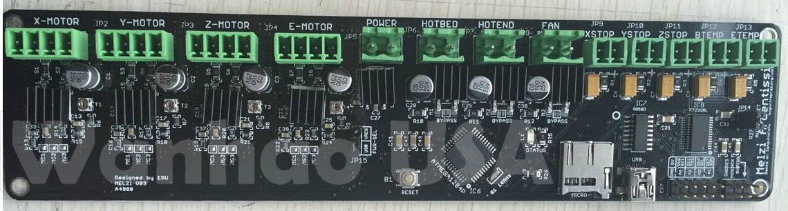
The Wanhao Duplicator I3 printer uses the Melzi printer board in the controller box (see Melzi info on RepRapWiki). The stepper drivers are A4988 chips. The board is powered from 12VDC which is then regulated down to 5V by a 7805 linear regulator (DPAK surface mount with heatsink). The power for the SD card is robbed from the FTDI 3.3V power.
Since the SD card is powered by the chip that provides USB communications to the board. When you plug in the card, this causes a tiny power surge that resets the chip, that in turn resets the main processor and causes the firmware to reboot (the beep and fans turning on for a second and if you were paying attention, the LCD display shows the Wanhao logo- a clear sign that ONLY happens when the firmware reboots). This is normal and expected. A side effect is that the firmware checks the SD card slot on reboot so it kind of auto mounts the card upon card insertion.
The I3 uses the Melzi controller board.
V2 Units
The Melzi boards on the newer units have been changed (the harness connections) and have also been reported to have temperature fluctuations while printing. The fluctuations appear to be cosmetic but there is a fix that involves soldering one or two jumper wires on the Melzi board.
LCD Pins / EStop:
There is ONLY the 10 pin LCD connector and the ICSP port.
In the LCD standard in the Reprap community, there is LCD (SPi protocol so at least 3 pins) you go the encoder+ click, so that’s 3 more pins, then you got beeper 1 pin, and Estop is a standard in he interface 1 pin. If 2 pins are power and ground, that’s all 10 pins accounted for.
The only other connector is the ISCP and that’s in parallel with the SD card.
NO in most Repraps, the Estop is just an input to the firmware to reset and there are options on HOW the firmware handles it. NO it is not a power kill, but on some boards it can command a power supply shutdown. Melzi doesn’t have any free pins to control a PSU. . This is the low end of the Reprap open source. The Melzi is meant to be a low cost no extra options kind of board. It works, it prints well, but it is NOT every bell and whistle option. That said, it follows standards established in the Reprap community. It runs Reprap firmware. The LCD interface board follows the minimum number of user control inputs- LCD, encoder+click and Estop along with alarm or beeper.
| Header Pin | I/O Pin | Description |
|---|---|---|
| 1 | D17 | LCD CS |
| 2 | A1 / 30 | Encoder B |
| 3 | D16 | LCD Data |
| 4 | A2 /29 | Encoder A |
| 5 | D11 | LCD SCLK |
| 6 | A3 / 28 | Enc Button |
| 7 | D10 | ESTOP |
| 8 | A4 / 27 | Beeper |
| 9 | +5 | LCD Power |
| 10 | GND | Ground |
Extruder Information
MK10 Style
Replacement Extruder assembly from Uncle Chuck
All Metal Hotend kit from Micro Swiss LLC
Hotend Thermistor
100k 3950 Thermistor Screw in replacement #1 (eBay) or Screw in replacement #2 (eBay)
Fans
Extruder Cooling Fan
Connector: 2pin (3pin adaptor included) (We only need 2 wires fans but can use 3 wire fans and ignore the 3rd wire)
MTBF: 30,000 Hours
Noise: 14.00dBA -Nice quiet fan!!!
Airflow: 4.11CFM (Correct airflow of 4.0CFM or better)
Rated Voltage: 12V (correct 12V rating)
Rated Current: 0.06A (current is a non issue)
Dimensions: 40.0 x 40.0 x 10.0 mm (correct same size as original)
Filament Cooling Fan
Rated Voltage: 12V
Dimensions: 30.0 x 30.0 x 10.0 mm
Heated Bed
12V MK3 Aluminum heated bed
MK3 heated bed from Robotdigg
MK3 heated bed from Amazon
Material:Aluminum Plate
Voltage:12V/24V
Max Temperature:180 Degree Celsius
Dimensions:214mm x 214mm
Thickness:3mm
1 Layer 35μm (1oz base) Copper
Resistance between 1.4 and 1.6 ohm for the 12V
Resistance between 5.0 and 5.4 ohm for the 24V
Repetier Firmware
Repetier Firmware configured for the I3 Melzi Board and LCD
Download then unzip the file Wanhao_DupI3_v0923.zip. Open the INO file in the Arduino IDE (known to compile with v1.6.4).
You will need to set the board type to Sanguino W/ATmega 1284 16MHz
After compiling upload to the board. This is only possible if you have a newer board with the Bootloader on it. If there is no bootloader then you will need an ISP programmer.