Description
The goal of this guide is to assist users in trouble shooting image problem when setting up and printing with the WanHao Duplicator 7. There are a number of methods to display an image on the LCD, everything from just plugging into a computer and configuring the screen to show a background image from the computer or even a Raspberry Pi connected. The goal of all methods is the same, to ensure that the 3 most common modes of LCD failure are addressed: mechanical (cracks to the LCD itself), configuration (settings), and electrical (ribbon cable connection). By either using just a background image or setting your desktop to solid color background such as all black or all white and using a sheet of notebook paper to better observe the UV image passing through the LCD can determine if you have a screen error and the corrections to attempt.
The initial batch of the WanHao Duplicator 7 does not appear to use glue or other mechanical attachment of the LCD protective overlay and actual LCD module. They are made of extremely thin yet tough glass, not unlike the typical smartphone screen and digitizer. The current screen as a rubber silicone like layer around the edges that conform and help to hold it in place in the lower milled aluminum base plate of the printer. The vat resin tray and FEP film come into direct contact with the LCD for maximum sharpness of the resulting imaged layer in resin. Overall, this structure can work well to produce outstanding high resolution prints. The problem is that when removing the vat resin tray and FEP film, a suction action can occur that lifts the entire LCD module from the lower base frame of the printer. When this happens, the LCD glass module that is attached under the protective layer and was recessed into the pocket of the aluminum plate can now lift out and become misaligned, and massive pressure is exerted on the glass if it is pressed back into the milled pocket with the slightest misalignment. This can and often does crack the LCD.
In addition to the potential to crack the LCD, it is also possible to not have correctly configured the settings to display the image on the LCD .
A third error that is possible with the LCD is that ribbon cables carrying the signal to the LCD can be only partially connected and this can cause a number of display problems.
Each of the failures has unique and somewhat tell-tale symptoms in the images.
Properly Functioning Screen
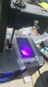
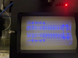
Here is what a good image of a layer looks like on the computer and then a nice and correctly displayed UV image on the LCD.
The same image now displayed correctly on the UV LCD.
Cracked Screen
Here is an example of a screen that has a tiny crack in the corner from accidentally lifting up and then the LCD cracking on an edge of the metal housing.The first sign is that using a standard sheet of white paper and sending an all white desktop background image to the LCD, the corner is clearly cut off showing the now non-functional cracked area. Glass normally cracks in curved sections and seeing this in a corner is a very bad sign the LCD has been damaged.
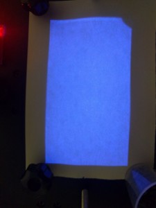
Here is the same cracked LCD showing images, and beyond the corner being non-functional, this also affects the rest of the screen and causes stray UV light to pass through that is not part of the desired image for that layer. You can see the faint lines and light seeping through the LCD as shown through this white paper. The actual image itself of the layer has sharp high contrast edges. You can also see that cracked curved line in the corner and while the layer image doesn’t enter that part of the screen, the damage from that crack is causing problems throughout the image making printing difficult if not impossible. Any stray UV light will cure the resin and on a properly working screen, there will be no stray light.

LCD Ribbon cable error
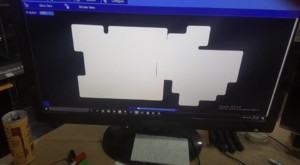
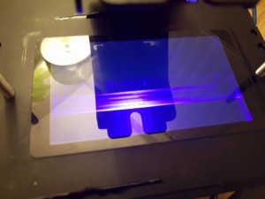
The other error that can happen is an electrical connector issue of the LCD to the actual HDMI controller board. This is a small ribbon cable connector that converts the tiny connector on the LCD ribbon cable itself to the wider style used by the controller. Because the screen is such high resolution, the screen is actually 2 separate controllers and entirely separate “channels” of the display. A common symptom of the connector not being seated is one hald of the entire display is non functional. This is noted by a very sharp but clear one half of the screen works and the other does not image.
An all white layer and the LCD is only showing one half of the screen.

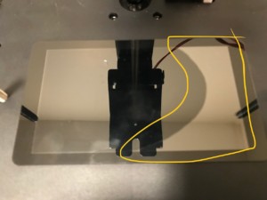
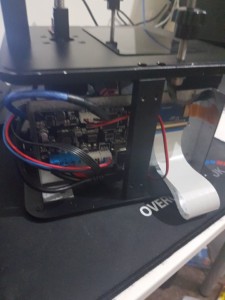
Here is a view of the printer base opened and the white wide ribbon cable connects to a small PCB and then the copper smaller ribbon cable from the LCD connects to the breakout board with a press in style connector. Both the wide ribbon cable connector or the press in smaller connector are fragile and must be handled with caution. Generally, reseating both the wide ribbon cable and the smaller press in connector has resolved the half LCD screen issue.
LCD Panel Separating from Glass
If too much pressure is applied on the top of the screen there is a risk of cracking or in this case pushing the LCD away from the glass which causes an air gap. The symptoms are a shiny area where the separation has occurred. This can sometimes be fixed by removing the metal reflector below the LCD then with an eye glass cloth or something lint free and soft, press upward on the bottom of the LCD screen from below while pressing down on the glass. You want to do this in such a way as to not put a lot of pressure in any one spot.