Description
The 30 Watt UV LED gets pretty warm and needs to be cooled so it will not burn out. The current models of the D7 appear to run warm after time and it is thought that the issue could be related to the way the cooling fan / hot-sink and airflow interact. The air is drawn in from the cooling opening in the base of the printer but the issue seems to be that there is a very large gap between the cool air entry and the actual cooling fan and heat sink. There is also no good hot air exit and the warm air inside can be circulated back into the fan instead of cool air.
Solution
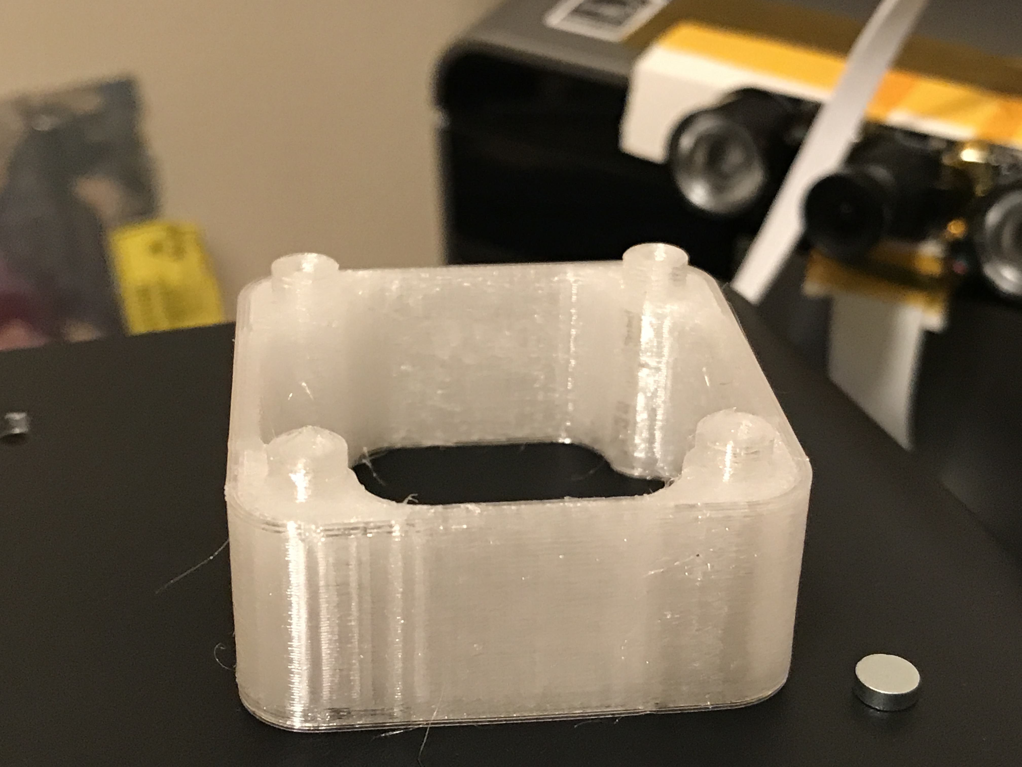
I designed a quick air intake shroud that serves two purposes. First it replaces the standoffs and lowers the UV LED by about half a millimeter which can help to keep the UV LED away from the metal reflector which can rub on the LED and possible short out. The second purpose is to direct cool air coming in from the bottom opening up to the fan and across the heatsink. This also blocks the warm air from being recirculated back into the fan. You will need to download and 3d print the shroud STL file before hand. If you need it printed check with someone with an FDM printer (could be printed on the D7 if the resin will take an M3 screw without cracking), or order from my 3dhub or PM me if you need one printed.
Update: If you want a simpler solution that does not require taking the UV Fan assembly apart then see this two part fan shroud by DaakTwo on Thingiverse.
Parts Required
- Printed STL

D7 UV Fan Shroud
- (4) M3x10mm screws (to secure the shroud to the base since the standoffs were screwed in from the topside). You can get a variety pack from Amazon (click on image below) pretty cheap and if you do much with 3d printing you can never have enough.
- Allen keys (two sizes, one for the M3 screws on the base and a smaller one for the M3 screws on the UV LED)
- Philips screwdriver to remove the front plate.

Installation
Installation requires access to the UV LED. This will require removing the front cover and removing four screws from the bottom base to allow for easier access.
- Remove all the cables (power, HDMI and USB).
- Remove the VAT, especially if it has resin it in 😉
- Start by removing the front faceplate be removing the front two screws on the front section on each side.
- Carefully move the front cover to the right side. This can be done with the switch still plugged in if careful.
- Set the D7 on its back so you have access to the bottom plate. By removing the bottom plate you can get access to the screws holding the UV LED down without taking the top and metal reflector off.
- Carefully remove the LCD ribbon cable from the small ribbon cable adapter board so it will not be bent or damaged while the base is being removed. The end of the cable lifts off of the small board stuck to the left side.
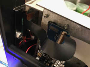
D7 LCD Ribbon Cable Removal
- Remove the four M3 screws that hold the thick base plate to the two side vertical brackets (two on each side) and pull the base plate forward just enough to get access to the two screws on the top right of the UV LED.
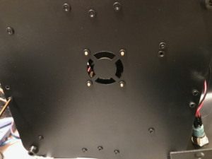
D7 Base Plate
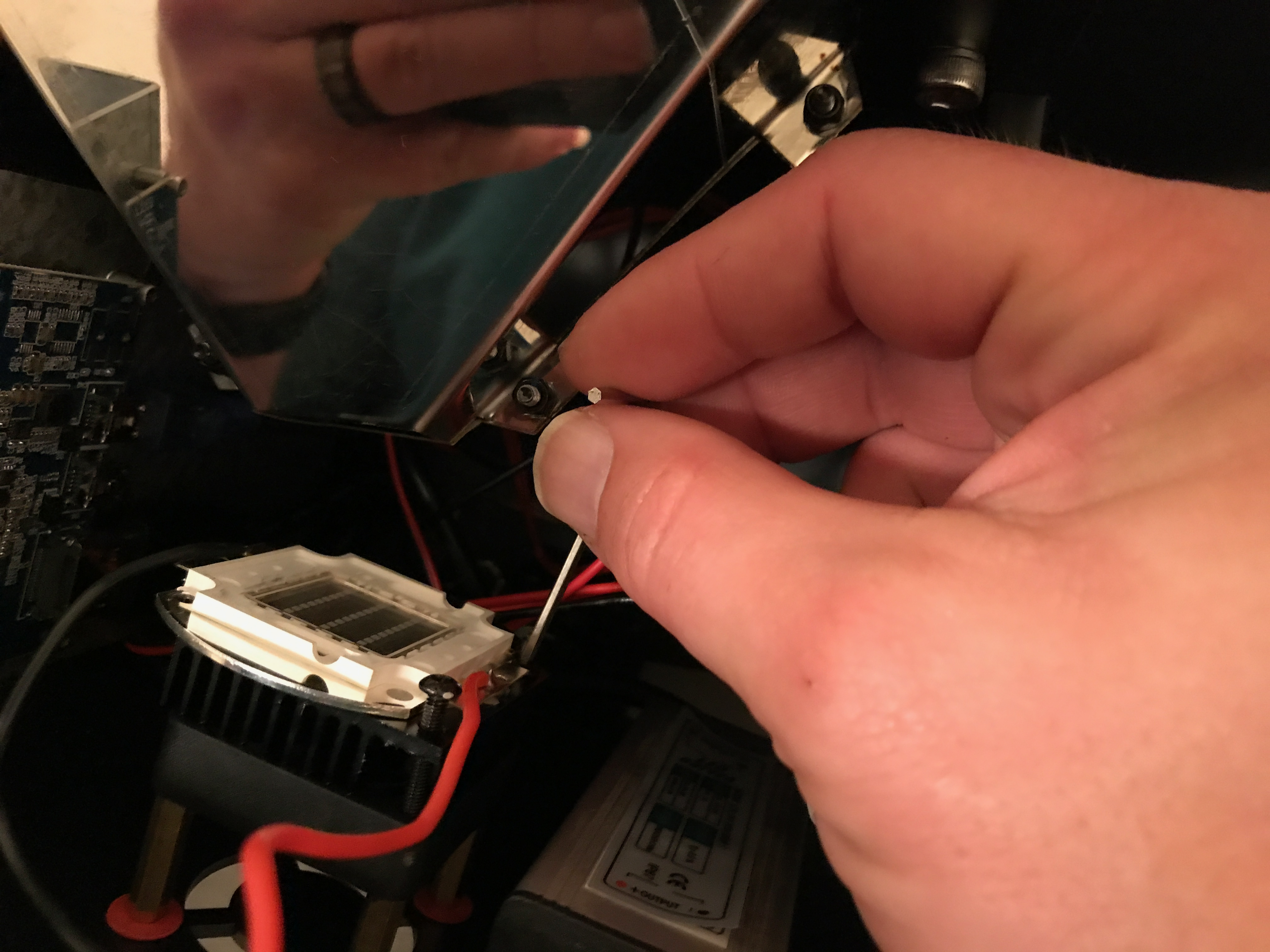
- Remove the two screws that hold the UV LED to the Fan, heatsink and standoffs. Carefully lift the Fan, heatsink and UV LED off as one unit keeping the two screws through them all to help hold them together and set the assembly aside.

D7 UV LED Removal
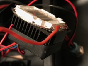
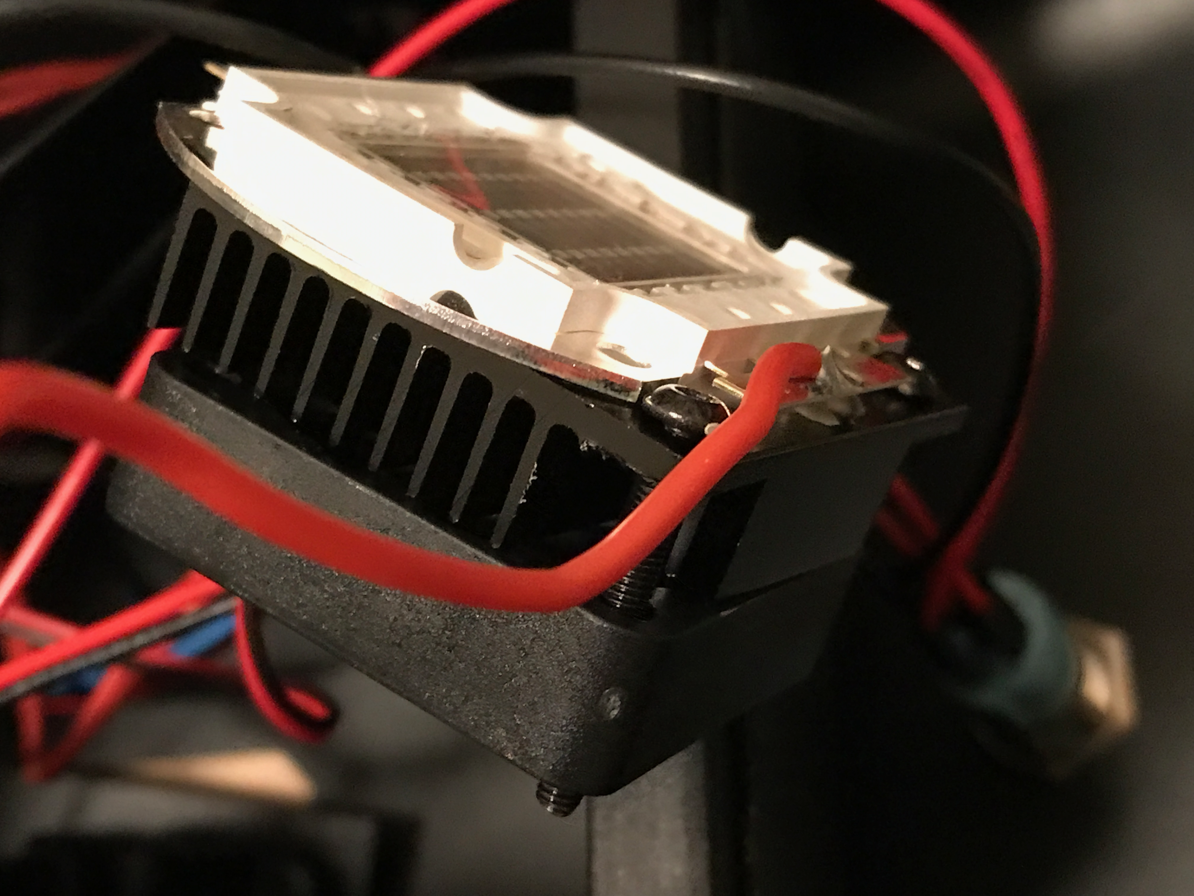
D7 UV Fan assembly removed
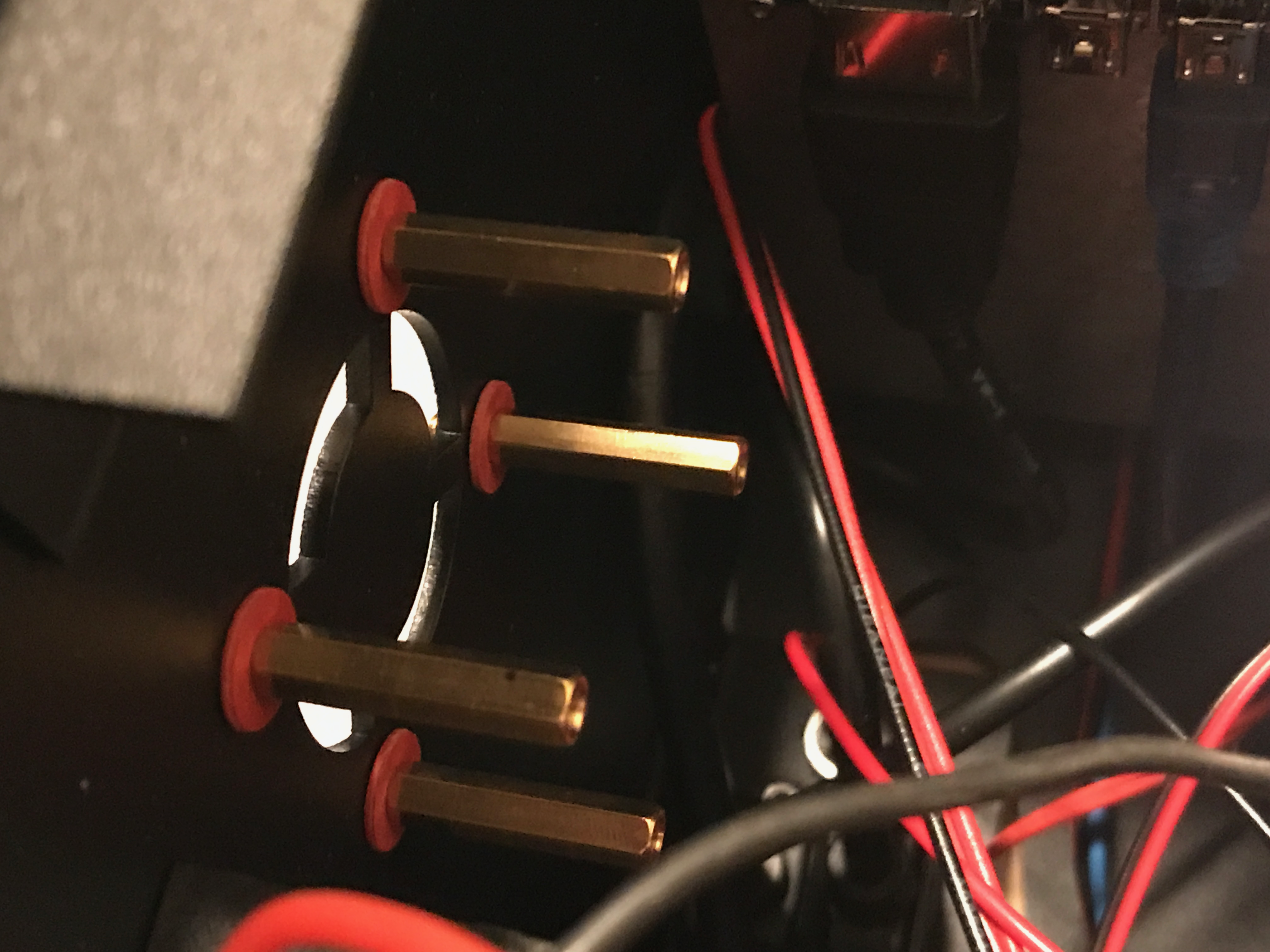
- Unscrew the four standoffs from the base that held the fan in place and remove them.
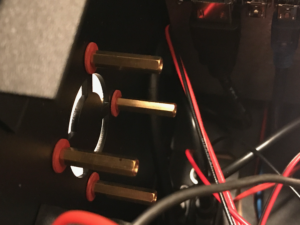
D7 Fan Standoffs
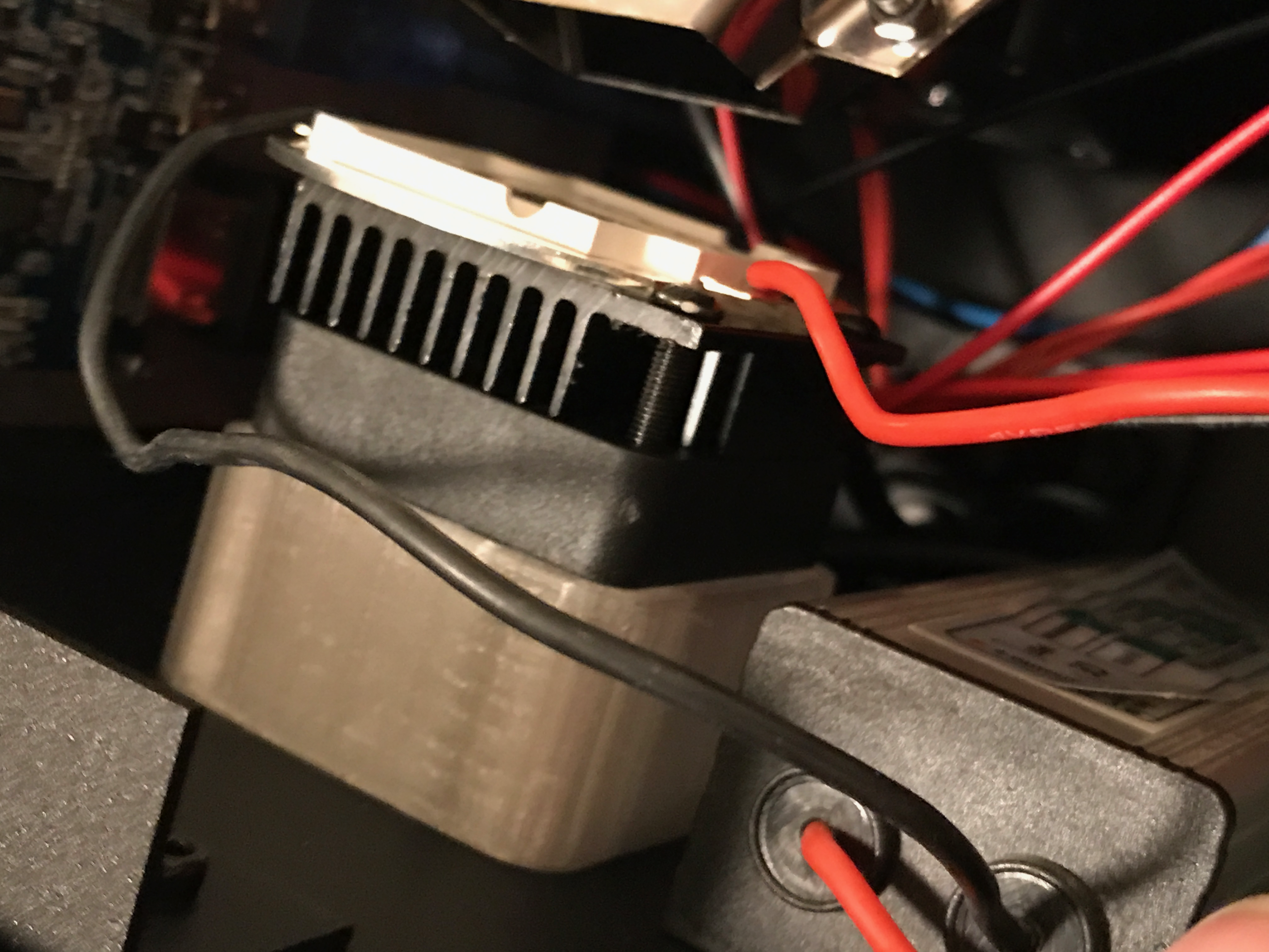
- Now would be a good time to check that the +LED power wire and tab are not too close to the heatsink. Check out this link for instructions on how to adjust it.
- Set the Fan / Heatsink and UVLED on top of the new fan shroud and use the original two screws to secure it. The holes are slightly undersized so the screws should self-tap, just be careful to not over tighten them.
-
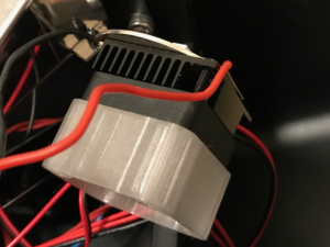
D7 UV Assembly on Shroud
D7 UV Fan Shroud
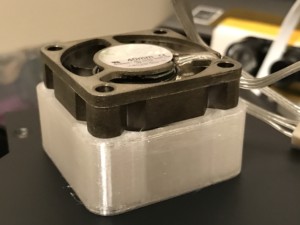
D7 UV Fan Shroud with Fan
- Take the four M3x10 screws and thread them into the base plate from the bottom until they just start to come through the other side. Since the holes on the base plate are threaded we will need to apply pressure from the top (hold the fan shroud down firmly) as you screw them in so there is no chance it pushes the shroud up instead of threading into it

D7 UV Fan Shroud Installed
- Re-attach the base plate with the four screws removed in step #7.
- Carefully re-attach the LCD ribbon cable to the small adapter board. The connector should plug straight onto the board will little force once aligned.
- Power up the unit and make sure the fan spins.
- Put the front panel back on and secure it then you are ready to go.