
Description
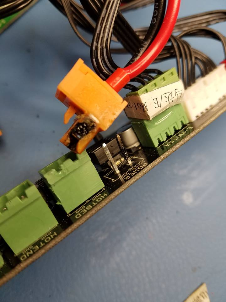
Burnt Hotbed Connector
The terminals where the hot bed wires screw / plug into the main board are known to burn or stop working. This is caused by the amount of power that passes through the terminal connectors which are not rated for this. If your hot bed stops working it is most likely this causing it. Look for burn marks on the side of the terminal connectors or loose wires. As many start to print other materials, increase their hotbed temps. This in turns puts more strain on the connections on the stock control board in our printers. This increased load will eventually start to melt and burn the stock connectors which were not rated for these higher loads.
One option to fix this, is to upgrade the connectors to XT60 type connectors which can handle the higher load. This requires removing the existing board connectors and soldering on new connectors. The MOSFET fix outlined below is meant to OFF-LOAD the power draw of the HotBed to another board completely. This will resolve any possible issues with the stock connections melting / burning. In laymen terms, the “MOSFET” is a switch which is able to properly handle the high power draw of the hotbed. It is controlled by the signal coming from the HotBed connection on the control board. This fix costs pretty much the same as purchasing the new XT60 connectors and can be done without soldering anything. The fix should cost $15-$20 depending on the location you purchase the board from.
Parts Required
- 14 AWG (gauge) Stranded Wire (for connecting the expansion board)
- Standoffs to mount and insulate the board from the controller (or a 3d printed mounting bracket). If you want to mount it external to the controller you can use something this enclosure.
One of the following or similar Hotbed Power Expanders. Here are some examples of possible MOSFET boards people have used. I have no recommendation here (others may).
- (from Reprapchampion) 3D Printer Heated Bed Power Module
- (from Banggood) Add-on Heated Bed Power Expansion Module
- (from Reprap.me) Hotbed Power Expander
- (from Amazon) Heatbed Controller MOSFET
NOTE: I take no responsibility for any of you electrocuting yourself or burning your house down. Please perform this at your own risk.
Procedure
(Updated) Here is a link to a very detailed install procedure by “The Nerd Channel”: http://thatnerdchannel.blogspot.co.uk/2017/06/mosfet-upgrade-wanhao-duplicator-i3-v21.html
Refer to the instructions that come with your particular hotbed expansion board (MOSFET board) for specific instructions on connecting the power, control and hotbed wires. See the photos below for examples of how it typically looks.
- Power off and disconnect all power from the unit (unplug the dang thing).
- Open the control box (screws on bottom and back of unit).
- Mount the new MOSFET board in control box. (You MUST use somTee type of stand-off to insulate the board from the control box or one of the parts below).
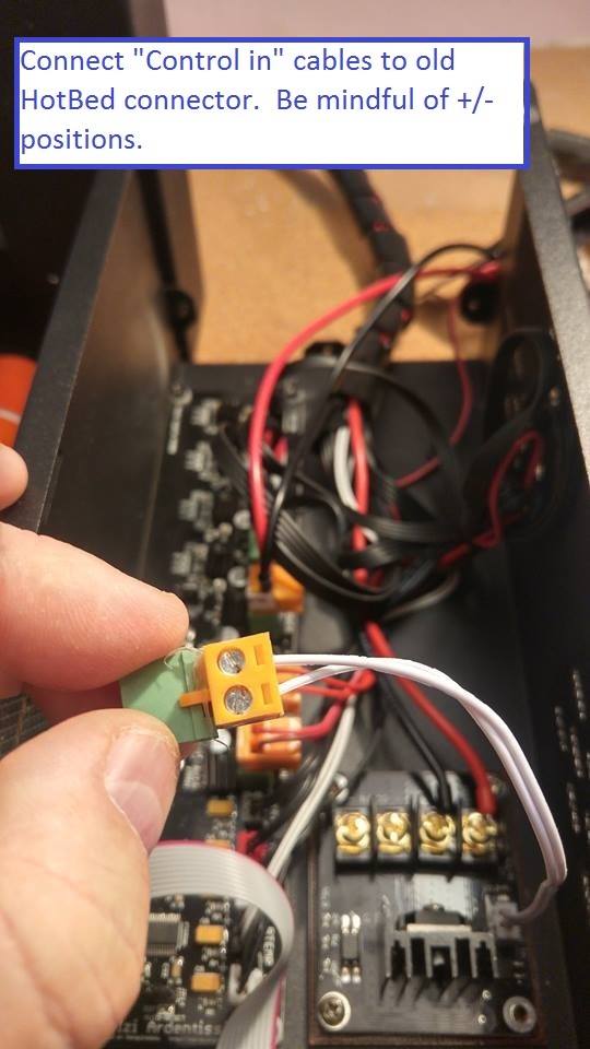
- Remove the HotBed connector and wires.
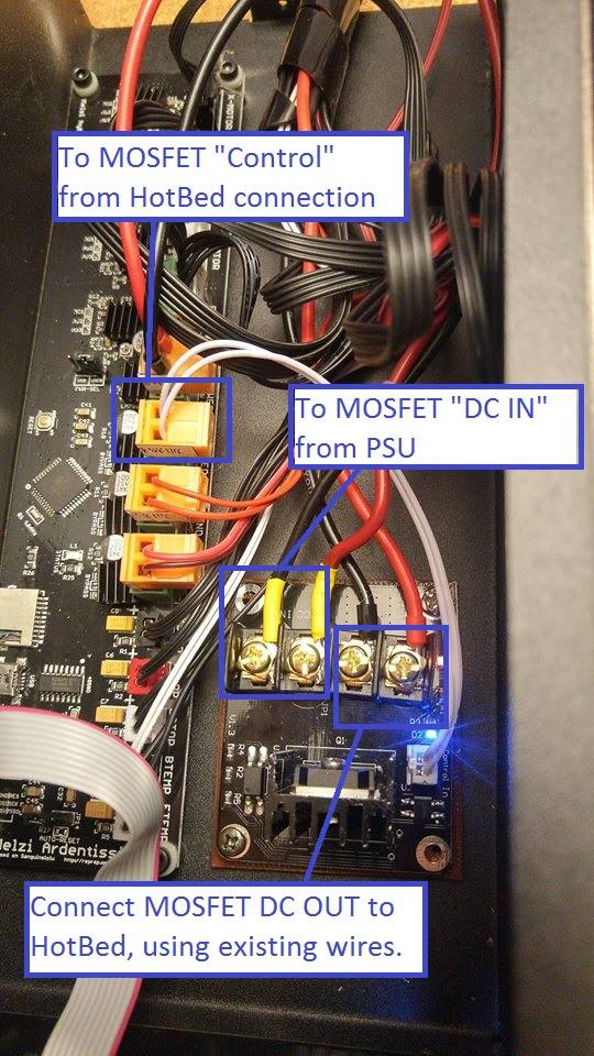
- Attach the Control wires from MOSFET to the Hotbed Connector and re attach the HotBed connector back to the control board (this step will depend on the revision board and connector style you have). Refer to the specific expander board you purchased for polarity and connection instructions.
It was noted that on the MOSFET board with the small white two pin header that the wires connect as follows:
White with Red dots connect to the Melzi Hotbed PWR pin and the White solid wire connect to Hotbed GND. - Attach two “NEW” 14 gauge stranded wire from the Power Supply (+V and COM) to the DC IN connectors on the MOSFET board. Be wary of polarity when connecting to your board.
- Attach the existing wires coming from the HotBet to the DC OUT on the MOSFET board.
- Close up and test.
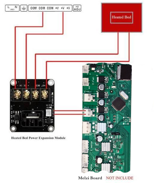 Hotbed Power Expansion Example |
 Hotbed Expansion Mounting |
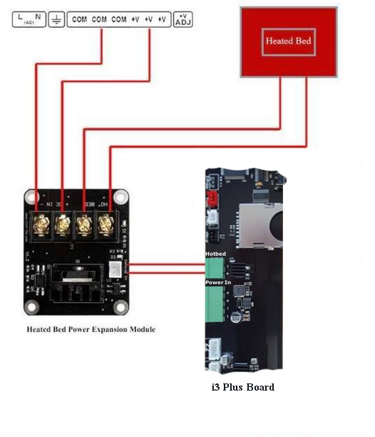 Heat-Expander-for-Plus |
 Original HB from Controller |
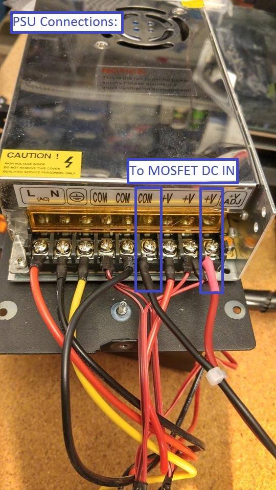 DC IN Power from PS |
 Wiring Overview |