
Adding a Glass Bed
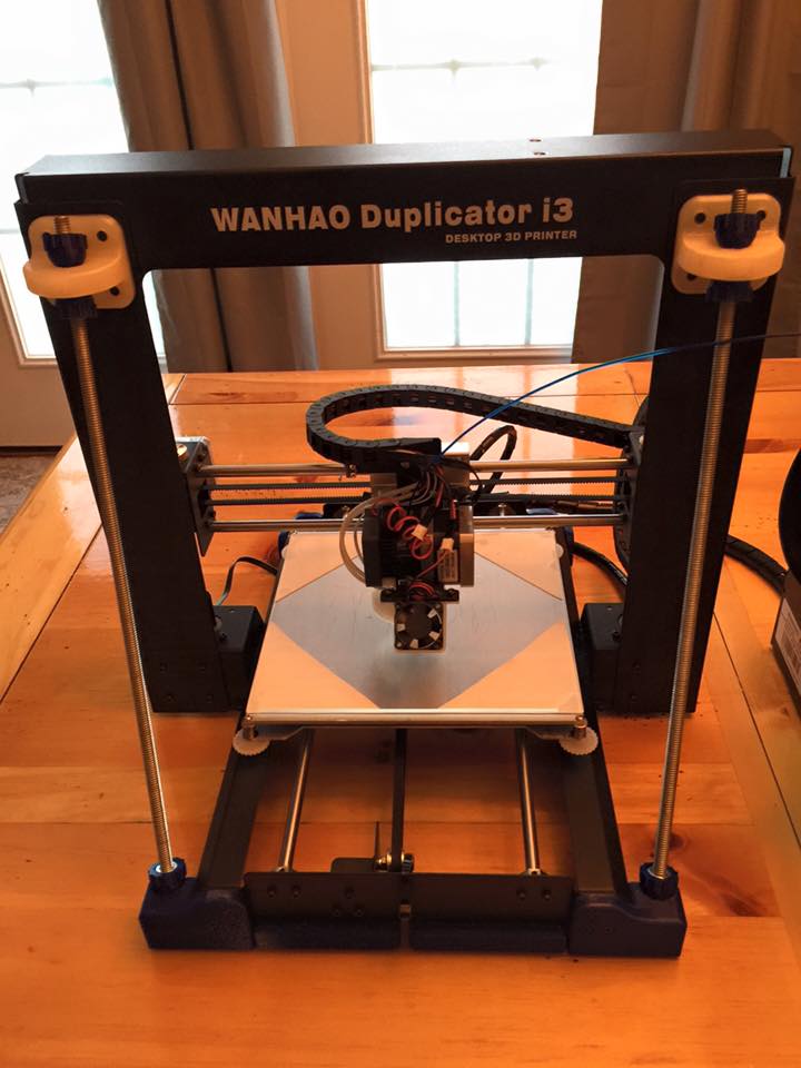
This modification applies to all versions of the Duplicator i3.
Description
On other printers, the problem in the past was the heater for the HBP was fiberglass circuit board and then an aluminum plate on top that had many screws that clamped the 2 plates together. Due to differing thermal expansion rates, the aluminum would try to expand but was constrained by the fiberglass that would then cause arching or or crowning of the aluminum plate when heated. Many folks complained.
This printer is different in that the heater is an etched circuit attached to the aluminum plate. This is a more advanced system and is quite impressive. That said, it’s still hard for any aluminum plate to be heated on one side, and then not have differing internal thermal expansion and warp and distort. I’m not saying there is a problem, I think is is just generalizing what can happen.
As such, clipping glass to an aluminum plate generally, does distort the glass slightly. I know this is hard to imagine but glass DOES BEND and flex. When trying to achieve sub mm precision across 200mm in X and Y, it can make a difference. So, using silicone square soft conformal pads lets the glass “float” and not be impacted by warping forces of the aluminum. It is strong enough the pad cannot slide in X or Y and thus cause a positioning error, but is generally sticky enough that the plate is semi difficult to remove meaning it shouldn’t accidentally fall off during handling and transit.
Again, the general problems with clips are: They rattle and buzz if the handles are not removed after install They can chip and crach the edge of the glass weakening it They are something for the nozzle to ram into Other things can catch on the handles sticking out if left on It’s cheap and awkward looking to be honest.
Using Silicone / “Ginopad” thermal heatsink pads
Using silicon pads instead of clips, will allow the glass to stay in place with no bending that the clips might cause. You don’t have to cover the whole surface with the thermal pad. Cutting it into 2″ squares and placing them in the corners and the middle work just fine. If you use a whole pad it may make removing the glas difficult. Don’t worry about the gaps where there are no thermal pads. The heat from the heatbed rises and the thermal pads transfer the heat also. The heatbed temperature is not as critical as the extruder temperature so a few degrees off won’t hurt.
Thermal pads under the corners of the glass.
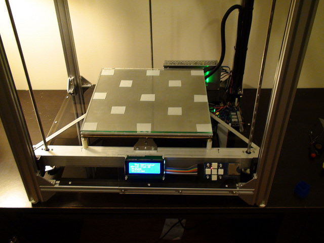
Thermal pads in a checkerboard pattern.
Notes on using Glass
Flatness. First layer height, AKA leveling, AKA tramming, is the single most important part of many prints. When you start printing at ultra low layer heights AKA high Z resolution prints, now allowable out of level first layer variations cannot be more than 50% of that layer height. So if printing 0.1mm layers, the max allowable variation as the nozzle moves across the entire 200mm by 200mm build are is a subset of that 0.05mm max Otherwise, the risk is the perimeter and infill won’t stick- you’ll get the waves on big flat infills and eventually break the whole part free in the first couple of layers.
Aluminum tends to crown and warp when heated, This is due to thermal expansion and because the center generally gets hotter than the outer edges, we get thermal distortion. By using glass and allowing it to float on the rubber silicone pads, the glass can remain dead flat at all times, where as the aluminum is allowed to ever so slightly deform. Because this deformation is so slight, it’s just enough that printing on the aluminum you’d see the error in first layer- where as with glass, it’s completely masked.
Other things like say you are printing an LCD control case and you want to top surface around the LCD bezel to be super smooth and almost look injection molded. If you print on tape with that part face down, now you get the texture of the tape in the print. You also have to be careful about first layer height as too high, you see the distinct infill lines, too low (near the bed) you embed the tape in the surface of the printed part.
Glass with a fresh smooth clean coat of dried hairspray can result in a mirror glass finish on a part that was touching the glass. By actually going too close with the nozzle, you can melt and merge all the first layer infill lines making it no longer look printed and like you injection molded at least that face of the part.
As I said earlier, masking tape offers ZERO protection from the nozzle in case of a print starting off with a bad leveling adjustment and scrapes the aluminum plate and also destroys the nozzle.
The same error on glass, the brass nozzle will just slide along the glass. Since glass is way harder than brass, it can never scratch the glass. Since it’s not metal on metal, the brass nozzle might be damaged, but also has a higher chance of surviving depending on how bad the whole incident was.
Yes, masking tape is an easy to use surface and generally PLA sticks well. It is NOT good for ABS in most cases. Glass however, is universal in that it can work for both PLA and ABS, as well as many other materials.
Materials Needed
Sources for Glass
- For the Duplicator I3 or MK2/MK2A style of heatbed (Glass is 220mm x 200mm):
Geeetech Borosilicate Glass from Amazon
Signstek Tempered Glass from Amazon
Borosilicate Glass from McMaster-Carr (203mm x 203mm x 3.2mm / 8″x8″x 1/8″)
- Or for around $3.00, you can have a piece of glass cut at local hardware store or glass specialty shop. Have them cut a piece 8.5″x8.0″ (imperial measurement) or 220mm x 200mm (metric measurement). The 8.5″ (220mm) side will fit the fill width of the bed on the X axis. The 8.0″ (200mm) side will fit just between the screw heads on the Y axis.