
This modification applies to all versions of the Duplicator i3.
Update: There is a new style of Z Brace but I have not tested it out. For more information and instructions go to: https://www.thingiverse.com/thing:1728621
Also see this page for a new Rear mount Z Brace mod.
Description
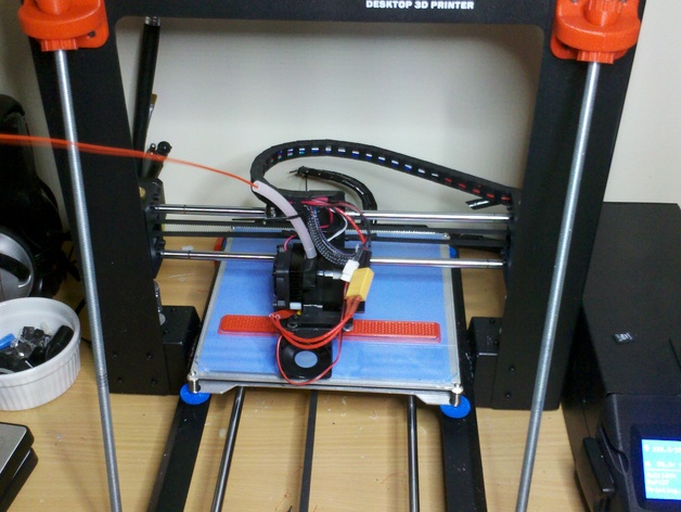
The design that allows the Duplicator i3 to be easily assembled with only 4 screws also results in a Z axis that can flex and wobble during printing. This modification will make the Z axis very rigid and will improve print quality.
Thingiverse link: Z braces for Wanhao Duplicator i3, Cocoon Create, and Maker Select
Materials Needed
There are two versions of the Z-brace mod. One versions uses one nylock nut in each front foot, the other uses a nylock nut plus an additional regular nut and ball. The version you decide to use will dictate some of the materials needed.
Hardware (find at your local hardware store)
- 5/16″ (or 8mm) threaded rod, ~16″ (or ~406mm) long (Qty: 2)
- 5/16″ (or 8mm) regular nuts (Qty: 4)
- 5/16″ (or 8mm) nylock nuts (Qty: 2)
- M3 x 10mm screws (Qty: 20)
- Adhesive rubber feet
3D Printed Parts
You can print all the parts together in “Plate1.stl” or print them individually as listed below.
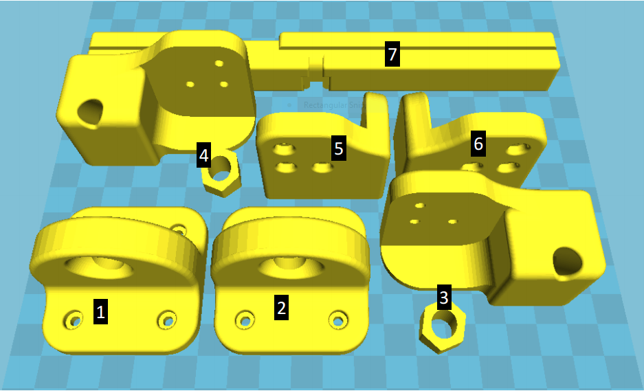
Z-Brace “Plate 1”
- “TopRight_fixed.stl”
- “TopLeft_fixed.stl”
- “BottomLeftForOneNut_fixed.st”
- “BottomRightForOneNut_fixed.stl”
- “BackFootLeft.2.2.stl”
- “BackFootRight.2.2.stl”
- “Front_Y_Brace.3.stl”
In addition to the parts above, you will need to print 4 of your chosen style of ball.

Z-Brace Balls
One is smooth (#8 – “Balls.stl”), the other has grips (#9 – “BallsMK2.stl”) to make turning it easier.
Process
Install the parts as pictured. For reference, you can download and print this PDF file.
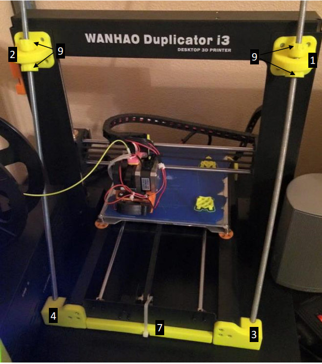
Z-Brace Front

Z-Brace Rear
After installing the braces onto the printer, use a tri-square or carpenter’s square set the tower square to the base. Squaring the upright arms to the table may work, but for best results, remove the heated bed and place one leg of the square on the lower plate and the other leg against the X axis rods. Adjust the two nuts on the top parts of the brace until the square is touching both X rods equally (use a sheet of paper or a thin feeler gauge). Check on both sides and center of the build plate. Re-install the bed, make sure the X axis is level by raising it until both sides are seated firmly against the upper Z axis end stops, then “Home All” and re-level the bed.