
This page contains a lot of the common questions and answers related to the Di3 printer. If you have a question would like answered or have information that you would like to add to the Faq page, use the request form to send the information.
Wanhao Di3
FAQ's related to the Wanhao Duplicator I3 Printer
Make sure the rods on the Y-axis are level. I was having the same problem . I loosened the nuts and applied gentle pressure, raising the ends of the rods to the top and tightening the nuts. Now, I can get all 4 corners to level. I put a bubble level across the rods and made sure the front and back of the rods were level to each other.
The gap with the springs inside – that is not a reliable way to ensure it is level (the aluminium plate below can bend separately from the warping by the heatbed, giving very inconsistent results).
They way I do it:
- Get yourself a Feeler Gauge (on Amazon or your local car spare dealer). You want at least a leaf of the layer height you will be using (for example I level with a 0.15mm gap, so I need the 0.15mm leaf/blade). I have a full set so I can change it very easily when I want
- A feeler gauge is simple a few leaves of preset thicknesses, which you can place into a gap to determine the size of the gap. By having an adjustable gap, now you can adjust it to be a very specific size.
- Now level your printer and print out 2 identical posts – http://www.thingiverse.com/
thing:1138928 - Follow their instructions to make sure they are as close to identical as possible.
- A good idea is to mark each so that you will know which side you use for which post (keeping thing here consistent will improve results).
- Guide for Bed Leveling: https://3dprinterwiki.info/
wiki/wanhao-duplicator-i3/ duplicator-i3-calibration/bed- leveling/
- Now place these posts under the X-rods (as shown in the picture they have).
- Move the rod down onto the posts, and let both sides skip steps (the posts will keep the X-rods firmly in place, and after both skipped steps, they should be level in relation to the posts).
- Using the menu, move the Z axis up a few mm so that you can remove the posts.
- Now home the printer.
- Depending on which software you use to slice, you either need the gap to be 0mm (Simplify 3D) or the first layer height (Cura and others). If you need a 0 gap – it is difficult to level (how do you know it it just touching and not pushing down).
- Since I use S3D, I now command the printer through the menu to raise the Z to my first layer height (0.15mm), make sure you don’t use the fast option since that is full 1mm increments.
- Now level the printer:
- What I use for quite consistent results is to use the menu to move each axis to predefined places (use the order on the guide) to level that position:
- Front Left: X10, Y10
- Front Right: X190, Y10
- Back Left: X10, Y190
- Back Right: X190, Y190
- Go over the places a few times (since each change can affect the leveling of the others), until you find they remain correct.
- What I use for quite consistent results is to use the menu to move each axis to predefined places (use the order on the guide) to level that position:
- Now your bed is leveled in relation to your X axis, which should still (since we never disabled the steppers) be level in relation to your posts (which are repeatable).
Now you can print and test the leveling (remember glass can warp, which may through the leveling out in some places). You can also make minor adjustments until you get good first layers.
After prints, before you switch off the printer, raise the Z and place the posts in underneath, let it skip steps and then you can shut the printer off (the posts will keep it level and the next time you start the printer, just raise it again before homing).
This is how I have been printing the past few weeks (bit more than a month), and only did the whole leveling process when I moved the printer.
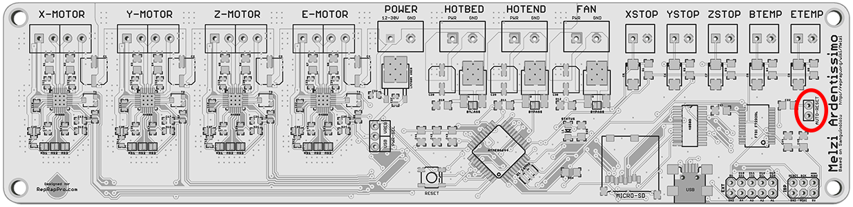
There is a Reset Jumper on the Melzi controller board that causes the board to reset every time the serial port (via USB) is opened. This can sometimes cause problems with the host software when it tries to connect to the printer. Removing this jumper can sometimes fix the problem. This involves opening the controller box and locating and removing the jumper shunt from the board. See the attached photo for a reference where the jumper is located.
A common issue is a broken wire going to the end points (wire got strained, bent too much or a whole range of other issues).
Another possible problem is the fan polarity (red and black wires) – if they are incorrect, you will blow the fan in seconds (trust me it is basically immediately – I blew one of mine).
Using your multi-meter (a very handy tool; at the very least you want to check voltage, resistance and continuity on 3D printers – if you need to buy one):
- unplug the wires inside the control box (always on wires should be the thin wires directly at the power supply, not running to the fan inside the box).
- unplug the fan at the top, you should now be able to check continuity (the resistance with a beeper function) on the wires (check the black wire then the red wire).
- The multi-meter should beep or indicate a very low resistance (maximum a few Ohms, anything higher is an issue). If it displays an open circuit (each meter show this differently), that wire is faulty and will need to be replaced.
When you plug the wires in, make sure the red is on the + terminal on the power supply, and the black on the CG/0V/GND (it will use one of these to indicate the black).
If you want to test the fan, a safe way I have been doing is to get a 9V battery, and place the correct wires on the correct terminal (if the fan is on – it works; even though it is a 12V fan, it should go on with 9V and 9V might not blow it immediately) – you might need to make or get an adapter if the fan wires have a connector on them.
Layer not sticking is most of the time a bed leveling issue.
Bed Leveling is not only the part to get it about the thickness of a paper from the nozzle, but also adjusting afterwards to ensure optimal layer adhesion. For a 0.2mm layer, you need to get the bed that distance in the position the nozzle will be when it prints the first layer (while the printer is printing the first layer – which is why we use extra lines of the Skirt/Outline option). This is the difficult part (some slicers use your leveling as the first layer gap, others add the set first layer height on top of your leveling gap [for these you need to account for it]).
Half of the first layer height, is how far off you can be from the ideal gap as an absolute max (for 0.2mm layer height, that is between 0.1 and 0.3mm). The Di3 uses M3 screws with a pitch of 0.5mm for bed adjustment – 0.1mm difference is only 1/5th of a turn.
The Di3 have one very big weakness: The X axis does not stay level. Since it have 2 motors, they can move independently while powered off (or disabled). Leaving the printer off or steppers disabled for more than a few hours is enough to have it shift slightly. I use http://www.thingiverse.com/
Bad filament can cause similar issues, but usually you can level a bit closer and it will still stick.
A glass plate is a very good idea and recommended – Adding a glass bed
Yes, your printer have the holes for the end-stop adjustment and thus adding the glass should be easy.
Placing the glass on top of the buildtak, not ideal (especially if you want to use the heatbed for PETG or ABS) – the buildtak on the printer have a paper based glue, which is very insulating. Real BuildTak is a vinyl type of product which conducts heat easier.
The easiest way to remove the buildtak on your bed:
- Heat it to about 50C (no need to heat the nozzle too), but leave it for a few minutes at 50C (so that the heat can get everywhere).
- Now carefully and slowly start peeling in one corner.
- If glue remains in a spot, you are going too fast (this takes patience, on my second try it took about an hour or more).
- After you have the whole sheet off, there might be residue spots left, using the glue side of the sheet, stick it on top of the residue spot (rub it a bit) and peel that part again (don’t stick the whole sheet, only a small part) – this should lift the residue off in no time.
Peeling it off cold will result in a mess (this is what happened on my first try – took 3 days to clean, and it left scratches from the cleaning).
There are a few ways to connect a computer to the printer. Repetier Host is a popular program for Windows, Linux and the Mac that allows control, printing, slicing and editing of the EEPROM settings. Other solutions are Pronterface, Simplify3d (which is a full slicer with control built in), or using a RaspberryPi with the Octoprint program installed. For a USB serial connection, use a baud rate of 115200.
Some Z end stops are damaged in shipping and the metal tab falls off. Sometimes this can be put back on but in most of the cases we have seen the plastic part is slightly damaged. Here is a video showing how the endstop metal tab is put back on.
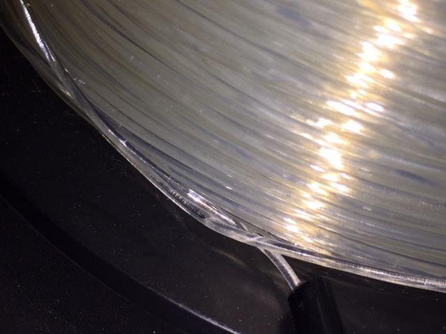
I figured I would post this so others could learn from it (although I know they have been told). I had a printer dropped off to fix along with a roll of filament to use to print some of Tim’s boxes. As the roll was being handed to me I noticed the end of the filament was loose and i made sure to instruct on the proper way to tuck the unused end in the holes in the side of the spool to keep from getting a knot and jamming during a print. Hours later I got the printer fixed and was trying to get a box print started so I could go to bed (1am now). Everything was looking good so I went to bed.
I woke up this morning and went to check on the print progress knowing that I would not have time to start another one before leaving for work since it started so late and my heart sank after seeing that only 1/2″ or so had been printed, which looked good I might add. I looked around to see what could be the problem and noticed a big knot right where the filament goes into the guide tube. This is what happens if you let go of the end of the filament and don’t immediately tuck it in the holes in the side of the spool. That is what the holes are for, so use them. I always unload the filament by pulling on it with one hand and wind it up with another but never let go of the end until it is secured. One evening wasted.
Securing Filament
Unless you have a really early model of the printer there should be two sets of holes where the Z end stop switch is mounted. Move the Z stop switch to the upper set of holes to provide room for the glass. The other solution is to use a printable Z end stop mod (see this mod page).
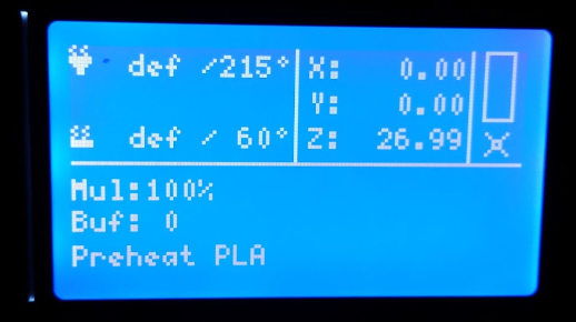
If you are seeing a “def” error message next to the extruder and/or bed temperature indicators on your LCD screen then you most likely have a thermistor problem. The thermistor is what allows the extruder and also the heated build plate to operate at a certain temperature.
Why are you getting the “def” error?: You have a bad/cut/melted/frayed/disconnected thermistor and/or thermistor cable. To find the problem spot you will need to inspect the thermistor and the thermistor cable carefully for anything that resembles a problem. The usual problem spot is at the point of contact with the heating block. This is due to the amount of heat that is generated from the heating block and also because there is pressure on the thermistor cable by the screw and nut set. Also be sure to check for a loose cable connector at the mainboard (micro-controller) as these are known to un-plug out of place.
The Solution: Once a thermistor is malfunctioning it should be replaced. However, if the problem is a cut or disconnection somewhere along the cable it can be repaired/re-connected. If you have never repaired a wire it is crucial that you ask us for help by contacting us at support@wanhaousa.com since this wire is what will regulate how much heat is transmitted to your extruder assembly (possibly very dangerous). If you have connected wire before then the procedure is standard: create 2 clean cut ends, pull back cable sheathing exposing the metal wire ends, take one of the ends and slide on heatshrink tube all the way past the point that will be soldered, solder both new wire ends to each other, slide heatshrink back over the solder point, shrink heatshrink, and lastly wrap in kapton tape for extra safety.
You can use binder clips, but that could cause the glass to bend with the aluminum. The recommended solution is to use silicone thermal pads under the glass (see corresponding mod page) . A few 1” square pieces spaced evenly is sufficient.
The switch may not be broken. The metal tab often comes off during shipping and can be placed back on. If the switch is indeed broken, contact your reseller for a replacement part. You may also be able to find the switch at a local electronics supply store.
There is a difference between leveling the bed and actually setting the correct offset / distance between the nozzle and the bed. Bed leveling is only half the process. Print a part with about 4 skirts with an offset of about 20mm from the part and watch that as it is printing and then you adjust the bed as it is printing accordingly. If the lines are not sticking then turn the wing nuts or thumbscrews clockwise if looking down at the bed. If they are really squished (you want some flatness) then turn them counterclockwise if looking down. You do that for each pass in in quadrant. You want to watch it for all passes because you need to check what it looks like between the lines since they should be touching.
The Wanhao factory website (http://www.wanhao3dprinter.com/) has a list of resellers around the world at. Additionally, some recommended vendors are:
- Uncle Chuck’s 3D Printer Stuff: http://unclechucks3dprinterstuff.com
- The Ultimate 3d Printing Store: http://ultimate3dprintingstore.com
- https://www.3dprintersonlinestore.com
This is a list of the screws that are commonly used and the size / specs for them. I always try and have a variety on hand for mods or repairs.
| DIA | LENGTH | HEAD | LOCATION | HEX |
|---|---|---|---|---|
| M4 | 16 | BUTTON | X-AXIS BELT | 2.5 |
| M3 | 5 | SOCKET HEAD | FRAME | 2.5 |
| M3 | 12 | SOCKET HEAD | 30MM NOZZLE FAN | 2.5 |
| M3 | 5 | SOCKET HEAD | 30MM NOZZLE FAN HOLDER | 2.5 |
| M3 | 40 | SOCKET HEAD | 40MM COLD END FAN | 2.5 |
| M4 | 9.5 | BUTTON | X-AXIS BEARING CARRIER | 2.5 |
| M3 | 3 | SET SCREW | X-AXIS RODS | 1.5 |
| M3 | 3 | SET SCREW | Y-AXIS RODS | 1.5 |
| M3 | 10 | SOCKET HEAD | Z-AXIS COUPLER | 2.5 |
- Cut the end of the filament off at a sharp angle so the tip is pointed

- Carefully straighten out at least the last inch of the filament out (PLA can be brittle).
- Make sure the extruder has been preheated and up to temperature for the filament you are using (ABS vs PLA / PET)
- Feed the filament in with the idler arm depressed (so that the v-groove bearing helps guide the filament to line it up with the hole). You should feel when it goes into the bottom hole and starts to have a little resistance. Feed just a little more by hand so you are sure the filament has been inserted into the hole correctly. You should see a little filament come out of the extruder nozzle.

I find it best to unload the filament by heating the extruder up to temperature then after the temperature has been reached press down on the filament tension arm and then push the filament down (feed the filament by hand) until at least 1/2″ has been push through the extruder then immediately pull the filament out. Unloading the filament this way helps remelt the end and get rid of the bulge that may have formed which can get caught between the pinch wheel and bearing as you pull the filament out. If this happens and the filament is hot enough the end may get broken off and left behind causing a blockage that may require taking the fan off the extruder to clear.
Video
YouTube video showing the unload process

More explanations from Jetguy:
Since you asked about unloading filament, here’s the answer:
PLA generally tends to get brittle overnight when it is curved on the spool and then straightened in the guide tube or path in the extruder. It might crack in the end right above or in the extruder the next day. ALWAYS extrude before unloading. In other words, on the i3, preheat, wait for it to reach extruder temp, I manually push down on the filament into the extruder and extrude at least 10mm of fresh filament, then press on the release lever and rapidly pulls up the filament while holding the release lever. ALWAYS cut off the melted tip before inserting the filament the next day.
Again, I cannot stress enough, ALWAYS, as a rule, a habit, even as a metal tick, extrude BEFORE removing or unloading filament. Do not power remove filament using the menu. Remember, you have MOLTEN plastic on the end of the filament. If you run that up back through the drive gears with the ilder bearing pressing against it, it will deform and might snap off inside the extruder between the drive gear and the lower plastic guide. Failure to follow this can lead to a major jam that requires taking apart the entire drive feed system.
The whole reason again I push down on the lever and manually extrude and then manually pull back, I can feel what the filament is doing. If when pulling back I feel resistance, i know i need to extrude MORE fresh filament before pulling back out. If you fail to do this, you likely will pull up molten plastic that always gets caught in the worst possible place in the feed mechanism and then you are having an even worse day.
Design Defect
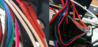
If you have a v1 model and have not fixed the cable chain heater wire issue then this may be your problem. This is the message from Wanhao:
We have one design defect which may cause the cable fire hazard. We request all Wanhao i3 customer check and correct the following point to avoid any possible hazard.DESIGN DEFECT: All the WANHAO i3 shipped before 27th Aug 2015 has the crimp(connection point between stainless steel cable and brass cable) inside the drag Chain. The drag Chain keeps moving can cause the crimp fatigue and break(check pic below). Then it can cause heating failture or circuit short.
SOLUTION


Video
ABS will not reliably stick to only a masking tape surface- and adding hairspray is no guarantee either. ABS is harder to print with than PLA because it doesn’t like to stick, requires extra attention to bed prep, really likes to be printed in a heated chamber surrounding the print with what you would consider rather hot air by comparison.
ABS should use 230C extruder and 100C heated bed temp but printing on the following bed surfaces: Kapton aka polymide tape Glass with a proven hairspray (not just any brand works) Glass with ABS slurry (ABS scraps melted in a glass jar using pure acetone from the hardware store, painted into a layer on the glass and let dry solid)
Conversely, PLA is very easy PLA uses 195C to 200C and 50C bed or optionally no heated bed It sticks easily to painters tape masking tape Glass with hairspray (best heated to 50C) And many other options like Kapton tape (also heated to 50C)
The newer models of the printer come with BuildTak installed on the heated bed. BuildTak is special surface (PEI) designed to allow various types of printer to adhere better. It is recommended that the surface be wiped down with alcohol between prints.
My preferred print surface is Glass with hairspray (specific brands). See this link for more information on installing a glass plate.
If your prints all of a sudden start printing 10mm off the bed and all other possible causes have been checked (Z endstop, gcode offsets, etc) then just try resetting the controller. This has happened to me a couple of times and been reported by others. The issue is unknown and seems to be a firmware glitch. For better instructions watch this tutorial: Resetting the controller
- The stock z steps/mm is slightly off on the default z steps per mm from the factory (405 vs 400). The math is easy:
- 16 (times micro stepping); 200 (full steps/rotation); 8 (thread pitch)
16 * 200 / 8 = 400 steps/mm (The default is 405).
Set this new value through Repetier Host. Without this change your parts will grow 0.0125mm for every mm in Z.
- 16 (times micro stepping); 200 (full steps/rotation); 8 (thread pitch)
- The first layer gap needs to be exactly what you slicer expects (and be perfectly flat):
- S3D will use raise the nozzle to the first layer height (so if it is 0.2, it will raise it to 0.2mm from Home) – this is the Zero Gap method (the gap at home should be 0).
- Cura and others use the Home Z as the first layer (so in this case you level it to 0.2mm gap).
Perfect extrusion.
- When everything is working in sync you can get perfect heights (but it is difficult and usually not required to be this precise).
There is a know issue that the screws holding the plug (with the switch and fuse) are sometimes too tight, causing a bit of bending, which in turn results in the switch getting stuck.
Slightly loosen the screws and try the switch again.
The MicroSD card that ships with the printer is known to be of a low quality. Replacing the MicroSD card with a higher quality card often solves this problem.
Yes, this is normal with the Wanhao i3 design. The most common fix is to cut a notch in the bearing block with a hacksaw as pictured. See this mod page for the complete instructions.
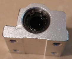
Bearing block mod

Another option is to replace the bearing block with a 3D printed one with the notch already cut out. You can download the file for the bearing block here: http://www.thingiverse.com/thing:1172838
A ball driver for the M3 and M4 is pretty much the next must have if you get into this hobby.
Here’s a list of my favorites L allen wrench set with ball ends on one end. L Wrench Set Ball Ends $10 well spent. These are harder and stronger than most- less likely to strip out and worth every penny.
Ball driver set. These make your life a dream when they can be used. I am lost and usually angry when I don’t have these handy. Ball Driver Set $16 but trust me, the ease of use factor- you’ll NEVER go back or regret these.
Not so much a big deal for this printer since all the factory screws tighten into threaded metal. But long term and even for the mod of using locking M3 nuts on the long Bed leveling screws, this is another must have. M3 nut driver with massive recess for long screws. Again, just doing the bed mod- this pays for itself in one usage. M3 Nut Driver $6 bit again, in the hobby, there are a million M3 nuts, and this is one of my most used tools.
GOOD side cutters. There is a difference, this is one of the best. Side cutters $10, but again, you’ll go through 3 pairs of cheap ones that are never as good as this one.
Recommended Tools for 3D Printing and Design
Harbour Freight is a great source for inexpensive tools. Amazon also has some good deals, especially if you are a Prime member. Email or PM me with any tools you find handy and I will add them to the list.
- Digital Calipers are a must. I use these all the time when designing parts. I prefer the next model up that has the auto turn off feature which will save your batteries and also turns on when you move them instead of having to press the button.
- Metal Ruler. I can’t live without my metric metal ruler. Once you start designing your own parts you tend to find it is easier to switch over to the metric system since most all parts of the printing process is metric.
![]()
Here is a pretty good explanation of the limiting factors with 3d printing and speed posted by Jeffrey Meyer:
The major limiting factors to the speed are dictated by a fellow named Isaac Newton et al – yes, the same guy who invented gravity.
Factor # 1: Newton’s 2nd law says that the force F required to accelerate a mass M to a speed V is proportional to the mass.
F = MxA
A is the acceleration – the time rate of change of V – i.e. if you change V in a short time, A is high.
In our case, let us look at a situation where we are printing the corner of a rectangle – our head is moving along X at speed V and we want it to stop the X motion and start moving along Y at the same speed. Stepper motors are driving both axes – i.e. as the name implies they move in steps, not continuously. This means that one X step before we reach the corner we have to decelerate from speed V to zero in one single step (a very short time). A is high means F is high. Similarly, we have to accelerate M to speed V in the Y-axis in one-step – again A and consequently F are high. For a high force from the stepper motor, we need a high current from the stepper motor driver electronics. In fact, the whole machine frame stiffness could be affected by these high values of A, resulting in slightly distorted prints.
Factor # 1 limitation is M (mass) and stepper motor driver current.
Factor # 2: The thermal power of the hot-end. In order to print more quickly you need to heat up more material to the print temperature. Simply said, the more hot-end heating power you have the quicker you can potentially print (not withstanding other limitations).
Factor # 3: Cooling and part size. This limitation is in direct conflict with Factor # 2. If you are printing a very small part then the next layer starts extruding before the previous layer has had time to cool sufficiently. So, you switch on the cooling fan that also cools the hot-end that now requires even more power to keep the melt temperature constant, and consequently more cooling is required …. By contrast, very big parts may not require any cooling at all.
Factor # 4: STL facet size. The STL file that you feed into your slicer consists simply of a collection of small 3D triangles (facets) joined at their vertices and edges. The slicer finds the points of intersection of these edges with the layer planes and joins them with a sequence of small straight lines, and then translates them into commands of how many steps to move each stepper motor. If the facet size is very big the print will reflect a curve as a polygon. For example, a circle may print as a hexagon. On the other hand, if the facet size is very small, the slicer will work very hard, the polygon will print accurately representing the base curve, but the output file (g-code) will be very large and the printer firmware may not be able to keep up with the number of g-code commands at the speed you want to print. In such a case, the head will hesitate periodically causing nasty blobs and cavities in the print.
So this may not be the answer you were expecting, but as the saying goes there’s no free lunch. Since there are a large number of variables involved, and you have to compromise between them, there is no magic formula to answer your question. You can dive in and experiment by trial and error, but if you understand the processes, you can reduce the number of errors.
PID (Proportional-Integral-Derivative) is a control loop feedback controller used to help machines make decisions. In this case, the decision of when to increase or reduce heat to the extruder. If the extruder is unable to maintain a constant temperature or cannot reach the desired temperature you may need to run the PID Tuning.
See this page for instructions for Extruder PID Tuning
UNDERSTANDING JERK SETTINGS
There’s a couple of ways to look at what the jerk settings do. From a dead stop, the jerk setting defines the first move rate the firmware will factor into the move planning, and it will accelerate from that rate as required. When already moving and about to make a change in speed or direction, the jerk setting defines the instantaneous step the firmware can make in the feed rate.
Visualize this on a motor vehicle. For the smoothest ride, you put the vehicle in gear and slowly let out the clutch and give it some gas to gradually accelerate from a stop. To corner nice and smooth, you slow down to a near stop to complete the turn and then gradually accelerate back up to the speed limit. All this takes time. If you’re in a hurry, you can drop the vehicle into gear without using the clutch and the vehicle will lurch forward. To save more time, you can screech around the corners almost to the point the vehicle goes out of control. Completing the turn, you might need to adjust the steering for a while to get the vehicle moving in a straight line again. In a similar way, the jerk settings allow you to set where in the range you want the printer to run – slow and conservative, or fast and bouncy. (Referenced from http://3dprintboard.com)
See the following page for links to the various mods available for the Duplicator I3 printer.
Temperature fluctuation fix for v2 Units with the newer Melzi boards (v4.3)
This is the “official” Wanhao response for now. If you have erratic temperature swings then this might be the fix for you. The newer boards (labeled v4.3) have a ground plane problem and cause the temperatures to vary greatly when the heater is turned on. If you have a Melzi board with a different version then this may not be the issue. Abdul Abdali was kind enough to put together the following guide that shows how to modify the board to help with the problem.
PDF of the Instructions: TEMP-FLUX-FIX-Rev.-0.011816.pdf
There are known brands of hairspray that work extremely well on glass beds. Aquanet is one of them. The key is looking for the ingredients to have PolyVinyl and PolyCo??? but not much when it comes to the extra stuff. Here is a page with the chemical details.
97 is a user defined thermistor – this is what was used to create the firmware since the other thermistors (like the 14) expects to be pulled up by a 4.7k resistor (the thermistor itself is the pull down of the voltage divider) and the original Di3 uses a 10k resistor for the pull up (thus the need for a user defined thermistor).
If you want to test a thermistor, you can (though that is a lot of trouble and if you already have correct temperatures at non 25C it should be fine – at 25C all 100k thermistors will show about equal, greater deviation the further away you are):
Go to the website http://www.thinksrs.com/
See what method is easiest to get the required information:
- You can measure 3 temperature/resistance points, to insert in the first block.
- Ideally the temperatures should be as not very close to each other.
- This will give you a Beta that fits the curve
- You can also enter the expected R(25C) and Beta values; then on the calculator part enter a temperature or resistance to be translated to the other (see if and where it would be on the curve).
Loud clicking noises while printing are usually indications that the extruder motor is skipping steps, This could be due to:
- First layer or two – nozzle too close to bed
- Later layers – extruder temperature too low (not melting quick enough)
- Trying to go too fast (stick to around 45mm/s) to see if the extruder can keep up
- A blockage/clog/jam in the nozzle (very common) or PTFE tube getting tired.
- The idler arm could be cracked at the joint near the screw or the idler bearing could be worn out or damaged. These are rare instanced but have happened.
The gear could be chewing up the filament, which gets the dust debris in the teeth and reduces grip on the filament, worsening the problem.
The dribble starts after the nozzle reaches PLA set temp ( 215 degrees) and extrudes by itself before starting the print. When the print starts the extruded dribble either sticks to the nozzle and/or snags the first extruded layer causing it to lift. On the other hand when a print is successful the nozzle continues to ouse hot filament.
There are a couple of things that may cause this.
The first would be to change the Ext0 Heat Manager to PID (a value of 1) from the default setting of Deadtime. This can be done using the LCD and going to the Configuration then Extruder settings. Make sure the settings are saved after being changed. Once this is changed you will need to do PID Tuning procedure. PID (Proportional-Integral-Derivative) is a control loop feedback controller used to help machines make decisions. In this case, the decision of when to increase or reduce heat to the extruder. See this page for instructions for Extruder PID Tuning
The second reason could be that the setting for the Max Drive to the heating cartridge may need to be increased. The default value is 240. Try changing it to 255 and re-running the PID Tuning.
The last reason could be because the earlier units shipped with a 6mm heater cartridge but the hole in the heater block it is inserted into is 6.35mm and the heater is not making good surface contact. There are a few methods to fix this from wrapping in aluminum foil to replacing the heater cartridge. See this page for changing out the cartridge.
In general, no, Amperage rating alone is not a valid indicator of a given stepper motor’s specifications for a specific duty such as an extruder motor.
You have to know the system and any limitations and requirements.
#1 the stock melzi board uses built onboard A4988 drivers that I consider an absolute max reliable current limit of 1.5A. Yes, the chip might have a higher rating, but thermal design of the board, the housing, the fans, the vents, and usage all come into play. Thus, I smartly de-rate the drivers to a sensible 1.5A
#2 stepper motor torque rating is a function of all 3 components. The stepper driver, the motor coils, and the rotor length and field strength of the magnets. NEMA17 is just an outer size specification and mounting pattern. Length of the motor is one of the variables and in doing so, determines the stack makeup of the rotor and how many magnets are involved. The coils produce the rotating magnetic field, but the field must be attracted and resisted by the rotor field.
#3 Just as the physical parameters matter, so do the electrical. Since we are talking about being driven by a current limiting and microstepping driver, it’s imperative to understand the relationship of the power supply voltage, the driver internal chopping function, the motor coil inductance and thus resulting resistance. The higher the inductance rating, the slower the motor can spin because the coils take time to energize and reach rated current. Resistance also limits the voltage and current and largely translates power to heat. Some chopping drivers do not react well to extremely low inductance and resistance (often found in higher current rated motors).
The bottom line is there is a very limited range of motors that will work well as an extruder motor in an i3. You want greater current than 0.8Amp, but less than about 1.3A as the upper limit. You want a motor about 5 Ohms or less but not less than 2.5 Ohms. It should be longer than the current V2 motor, but longer motors begin to cut into the X usable distance because they hit the frame on the i3.